Detailed process of Assembling Multi-Functional 4WD Robot Car Kit
| Wayne Chen
In this tutorial you will be taught how to properly assemble a Multi-Functional 4WD infrared remote control smart car.
This process is very interesting. I believe that for every Arduino enthusiast, this sense of accomplishment is unparalleled when you can assemble scattered parts into a car. Let's get started now.
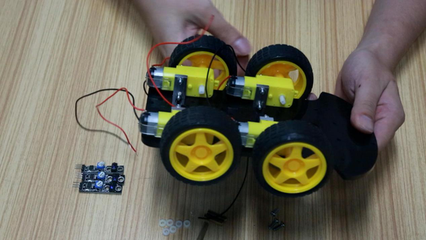
This is all the parts of a car. Below I will be divided into four parts to assemble the car.
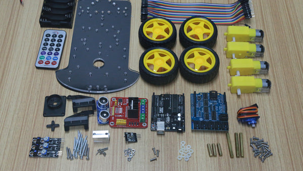
Part I Assembly of wheels, motors and tracking sensors
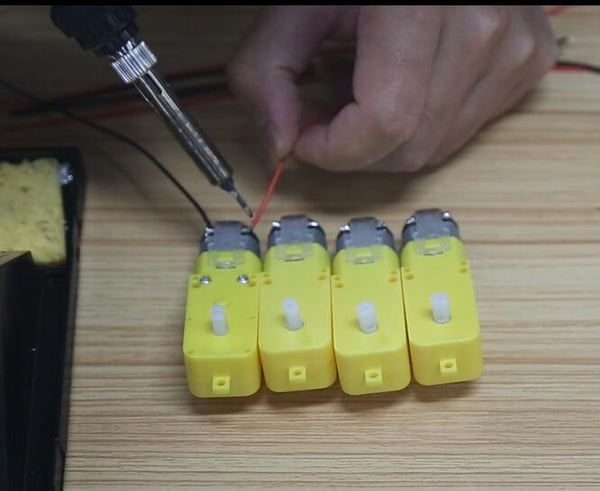
First, we solder the red and black power wires to the motor, and the soldering position remains uniform.
After soldering, connect the fixing post of the motor to the motor with long screws and nuts.
Note that the motor should be installed with the same direction as shown in the figure below, fixed with screws.

Mount the wheel to the motor.
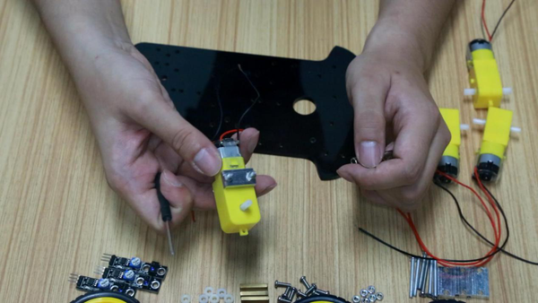
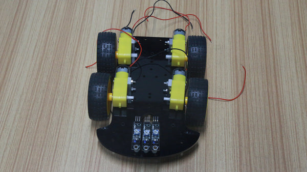
Next, install 3 tracing modules in front of the car.
Each sensor requires a short copper post and two plastic spacers.
This is to shorten the distance between the sensor and the ground, and the data obtained is more accurate.
The two ends of the copper column are fixed with screws.
Each sensor requires a short copper post and two plastic spacers.
This is to shorten the distance between the sensor and the ground, and the data obtained is more accurate.
The two ends of the copper column are fixed with screws.

Complete the first part.
Part II Installing the motor drive module
The motor drive module should be mounted on the opposite side of the motor.
Find two holes, use two plastic spacers under the board, and then fix them with screws and nuts.
Find two holes, use two plastic spacers under the board, and then fix them with screws and nuts.
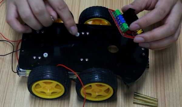
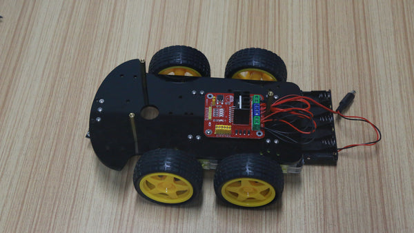
Complete the second part.
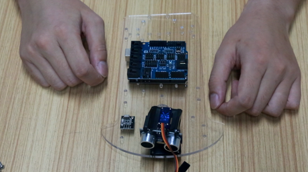
Part III Installation of steering gear and UNO board
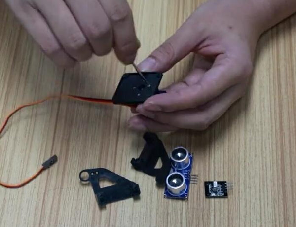
Install the rudder turntable on the steering gear, then fix it to the black bracket and tighten with 5 small screws.
Note: Turn the servos by hand so that the 90° position is facing forward and then fixed.
Note: Turn the servos by hand so that the 90° position is facing forward and then fixed.
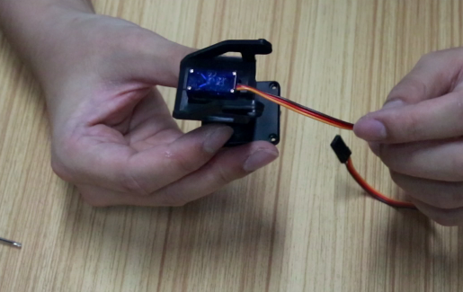
Install the brackets on the left and right sides of the servo, align the raised positions of the servo, and use two screws to fix the sides of the bracket.
Attach the ultrasonic sensor to the servo holder using two zip ties.
Fix the steering base to the front of the upper acrylic plate with thin long screws and nuts.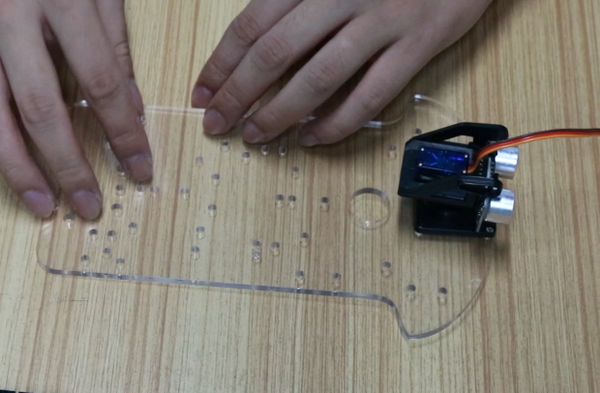
Fix the steering base to the front of the upper acrylic plate with thin long screws and nuts.

Install Arduino and expansion board.
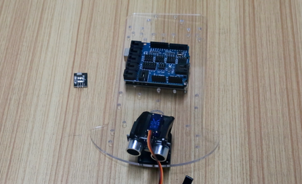

Install the receiver module of the infrared remote control next to the servo.

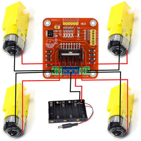
Part IV Connection
Motor drive module wiring diagram
Arduino pin connection table
| Ultrasonic sensor | ECHO | A0 |
| TRIG | A1 | |
| GND | GND | |
| VCC | 5V | |
| Servo | Orange line | D12 |
| Red line | 5V | |
| Brown line | GND | |
| Infrared receiver module | G | GND |
| R | 5V | |
| Y | D13 | |
| Motor driven module | ENA | D6 |
| IN1 | D7 | |
| IN2 | D8 | |
| IN3 | D9 | |
| IN4 | D10 | |
| ENB | D5 | |
| Tracing module | G | GND |
| V+ | 5V | |
| S-First | D4 | |
| S-Second | D1 | |
| S-Third | D2 |
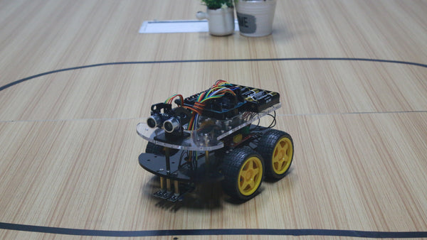
Finished!
Code
17 comments to
HI All,
Thanks for the video, it is very helpful, I followed the video for assemble the Robot car but i was bit confused with the Wiring part (video play time 10:13) onwards.. please provide support on the wiring part..
ни работает код
I found that this kit is fundamentally the same kit as the Elegoo Smart Robot Car Kit V3.0 and I expect it will work with the ElegooKit ios app (there’s probably one for android as well)
I bought the Smartbot car kit through inventr.io. It came with a CD with instruction and the motors worked with the programs supplied. The next chapter was about bluetooth control, but the control program is not in the app store. Is there another program I can use with my iPhone to control the car?
where can I find the code for the robot