3D Printed Time-plotting Robot
| Wayne Chen
This is the project we saw from Thingiverse and it was very interesting, so give it a try!
The cute time-plotting robot uses a dry-erase pen to write out the time on a small board, then erases it and rewrites the next minute, repeating the process every minute. Designed for DIY and hackers, plotclock is powered by 3 9g servos and it controls the robot arm through 3D printing hardware.
Item List
- K10 3D printer
- Kuongshun Arduino UNO R3
- 3 servos
- 1 dry wipe pen
- Multiple nuts, bolts, thread tap
3D printing
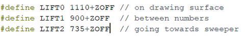
According to the provided stl file (3d print-plotclock), the parts are printed out using a 3D printer and assembled, note the direction of the servos and the range of motion of the 180° steering arm. After the servos is installed, the arm is attached to the steering arm. The screw cannot be tightened too tightly or too loosely.
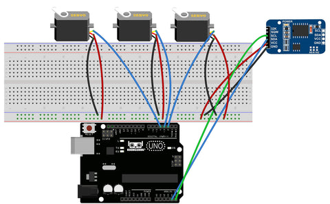
Wiring
The servo pin can be selected according to the code below.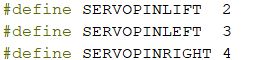
Debugging
After installation, start the calibration of the robot arm.
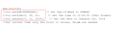
Add the 'DS3231' and 'Time-master' library files to your arduino library. Open the 'plotclock.ino' file.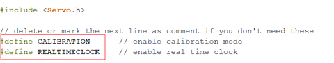
The second 'define' is the time to set whether to use the clock module. A fixed custom time will be used when the clock module is not used.
The first 'define' is to set the debug mode. In the debug mode, the two robotic arm servos start to move at about 90 degrees.
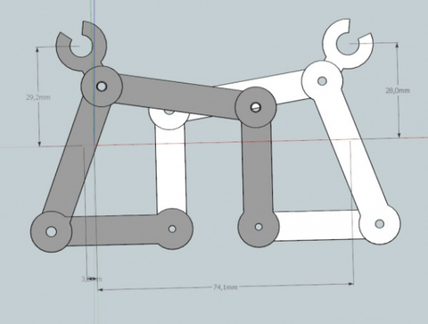
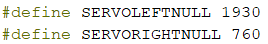
At this point, the robot arm is calibrated, the servo on the left side points to the front left and the servo on the right side points directly above, both are positive 90 degrees.
The figure shows the state when the left and right servos reach 90 degrees:


Schematic Diagram
Code Download
More information:
- German designer Johannes: http://wiki.fablab-nuernberg.de/w/Ding:Plotclock
- English descriptions: http://www.3ders.org/articles/20151003-plotclock-for-dummies-simplified-instructions-for-the-3d-printed-time-plotting-robot.html
- Thingiverse: http://www.thingiverse.com/thing:248009/#instructions
20 comments to
nzSBTUsRAIWbP
FNEjcXOyPZDWwAmS
jczEwRFYVvnfmd
JHmqpPMDVWUNju
hello.
Thank you for a great project.
The schematic is not connected from the Arduino VCC and GND to the breadboard. =)